ENGLISH
 FRANÇAIS
 РУССКИЙ
 العربية
 garyguan@tkdlkj.cn
Marine Diesel Generator Working Principles and Classification( part 2 of 6)
A marine diesel generator set is a precise combination of a diesel engine and a generator, converting fuel into electrical power through energy transformation. Understanding its working principles and classification methods is the foundation for proper selection and efficient maintenance. This article systematically explains the technical core of marine diesel generator sets — from basic components and working principles to classification systems.
1. Basic Components of a Generator Set
A marine diesel generator set is not a single device, but a complete power system composed of multiple functional modules working in coordination. To understand its working principle, we must first recognize the key components and their roles in the energy conversion chain.
Diesel Engine (Prime Mover): The heart of the unit, converting the chemical energy of fuel into mechanical energy through combustion in the cylinders, outputting rotational power via the crankshaft.
Alternator (Generator): Converts the mechanical energy input from the diesel engine into electrical energy, inducing AC voltage in the stator windings based on the principle of electromagnetic induction.
Control Panel: The "brain" of the unit, providing real-time monitoring of voltage, current, frequency, power, oil pressure, and coolant temperature, while controlling start/stop operations and protection functions.
Governor: Automatically adjusts the fuel supply to the diesel engine in response to load changes, maintaining stable speed and thus ensuring constant output frequency from the generator.
Cooling System: Dissipates heat generated during operation of the diesel engine and generator to prevent overheating. A closed-loop freshwater cooling system with a heat exchanger is commonly used.
Starting System: Provides the external force needed to start the unit. Large and medium marine generator sets typically use compressed air starting, while smaller units use battery electric starting.
These components form a tightly coordinated system: the starting system initiates operation, the diesel engine produces mechanical power transmitted via the coupling to the generator, which converts it into electrical energy output. Simultaneously, the governor maintains stable speed, the AVR regulates voltage, the cooling system continuously removes heat, and the control panel monitors and protects the entire process. A malfunction in any single component will affect the reliable operation of the entire generator set.
2. Diesel Engine Working Principle
Marine diesel engines universally operate on the four-stroke cycle. Each cylinder completes four strokes — intake, compression, power, and exhaust — over two crankshaft revolutions, ultimately converting the chemical energy of fuel into rotational mechanical energy at the crankshaft.

Four-Stroke Cycle Explained
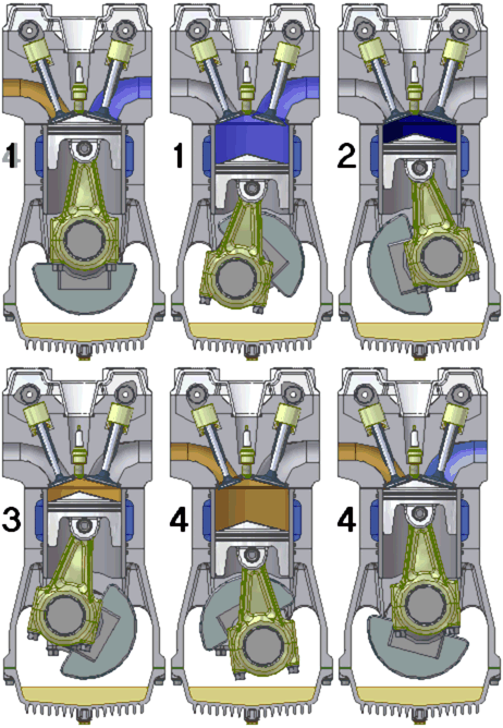
Intake Stroke: The piston moves from top dead center (TDC) to bottom dead center (BDC). The intake valve opens, and fresh air is drawn into the cylinder through the intake port. Cylinder pressure drops below atmospheric.
Compression Stroke: The intake valve closes. The piston moves from BDC to TDC, compressing the air. End-of-compression pressure can reach 3–5 MPa with temperatures rising to 500–700°C, creating conditions for diesel auto-ignition.
Power Stroke: Near the end of compression, the fuel injector sprays atomized diesel into the cylinder. The diesel auto-ignites (compression ignition) in the high-temperature, high-pressure air. The expanding combustion gases push the piston downward, producing power output.
Exhaust Stroke: The exhaust valve opens. The piston moves from BDC to TDC, expelling combustion gases from the cylinder and preparing for the next cycle.
Compression Ignition and Fuel Injection Atomization
The most fundamental difference between diesel and gasoline engines lies in the ignition method: diesel engines use compression ignition, requiring no spark plug. The high-temperature, high-pressure air at the end of the compression stroke causes the injected diesel to self-ignite. To ensure proper combustion, the fuel injector must atomize the diesel into fine particles at extremely high pressure (modern marine diesel engines can achieve injection pressures exceeding 200 MPa), spraying it into the cylinder for thorough mixing with air, achieving rapid and complete combustion.
Heat-to-Mechanical Energy Conversion
The thermal energy released by diesel combustion causes a rapid increase in gas temperature and pressure inside the cylinder. The high-temperature, high-pressure gas expands and pushes the piston downward. The connecting rod converts this linear motion into rotational motion at the crankshaft, which ultimately outputs rotational power. This process achieves the conversion of thermal energy to mechanical energy — the core of diesel engine power production.
Energy Conversion Chain
The essence of a marine diesel generator set is an energy conversion chain: Chemical Energy (Fuel) → Thermal Energy (Combustion) → Mechanical Energy (Crankshaft Rotation) → Electrical Energy (Generator Output). Understanding this chain is the key to grasping the working principle, and also helps quickly locate problem areas during troubleshooting.
3. Generator Working Principle
The function of the generator is to convert the mechanical energy input from the diesel engine into electrical energy. Its theoretical basis is Faraday's principle of electromagnetic induction: when a conductor moves through a magnetic field, cutting across magnetic field lines, an electromotive force (EMF) is induced at both ends of the conductor.

Stator Windings and Rotor Structure
A synchronous generator consists primarily of a stator and a rotor. The stator is fixed to the frame, with three-phase symmetrical windings (armature windings) embedded in its iron core slots — this is where EMF is induced and electrical energy is output. The rotor is driven by the diesel engine and rotates. When direct current flows through the rotor windings, it generates a rotating magnetic field. As the rotor spins, this rotating magnetic field sequentially cuts across the three-phase stator windings, inducing three-phase AC electromotive forces with sinusoidal variation in magnitude and direction.
Excitation System
The rotor windings require direct current to generate a magnetic field — this process is called excitation. The excitation system provides DC excitation current to the rotor windings and automatically adjusts the excitation current based on load changes, thereby maintaining stable generator output voltage. Common excitation methods for marine generators include brushless excitation (main exciter + rotating rectifier) and self-excited constant-voltage systems. Brushless excitation is widely adopted due to its maintenance-free operation and high reliability.
AVR — Automatic Voltage Regulator
The AVR (Automatic Voltage Regulator) is the core component for voltage stability. It continuously monitors the generator output voltage and compares it with the setpoint. When load changes cause the output voltage to deviate from the set value, the AVR automatically adjusts the excitation current: increasing it when voltage is too low, and decreasing it when voltage is too high. This keeps the output voltage within the allowable range, typically with steady-state voltage regulation accuracy within ±2.5%.
Frequency and Speed Relationship
The output frequency of a synchronous generator is determined by the rotor speed and the number of magnetic pole pairs, following the formula: f = n × p / 60, where f is frequency (Hz), n is speed (rpm), and p is the number of pole pairs. For example, a 4-pole (p=2) generator producing 50 Hz AC must maintain a speed of 1500 rpm. This is why the diesel engine speed must be strictly stabilized by the governor — otherwise, the generator output frequency will fluctuate, affecting the normal operation of electrical equipment. Marine power systems typically use 50 Hz or 60 Hz standard frequencies.
4. Classification by Purpose
Based on their role in the ship's electrical system, marine diesel generator sets can be divided into four categories, each with significant differences in power rating, installation location, and operational requirements.
Main Propulsion Generator Sets: Supply power to the main propulsion motor on electrically propelled vessels. These are the ship's largest electrical load source, typically with very high power ratings. They must meet the dynamic demands of propulsion loads that vary with speed and sea conditions, requiring high dynamic response capability.
Auxiliary Generator Sets: Supply power to daily shipboard electrical equipment (lighting, air conditioning, auxiliary machinery, communications, etc.). These are the primary power generation equipment on most vessels. Typically 2–3 units are installed for redundancy and parallel operation, ensuring that when one unit is down for maintenance, the remaining units can still meet the ship's electrical demand.
Emergency Generator Sets: Installed above the bulkhead deck, outside watertight bulkheads in a safe location. When the main power system fails, the emergency switchboard automatically starts the emergency generator to power critical loads such as emergency lighting, fire pumps, emergency communications, and navigation equipment — the last line of electrical safety on board.
Harbor Generator Sets: Small-power units used while the ship is in port, meeting the limited electrical demand during berthing. Since they operate in port, they must comply with strict port emission regulations. Some ports require the use of low-sulfur fuel or the installation of exhaust gas treatment systems.
| Type | Primary Function | Power Rating | Installation Location | Operating Characteristics |
|---|---|---|---|---|
| Main Propulsion Generator | Powers main propulsion motor | Large (MW-class) | Engine room | High dynamic response, follows propulsion load |
| Auxiliary Generator | Daily shipboard power | Medium (hundreds of kW) | Engine room | 2–3 units for redundancy, parallel operation |
| Emergency Generator | Critical emergency loads | Small (tens to hundreds of kW) | Above bulkhead deck | Auto-starts on main power failure |
| Harbor Generator | In-port power supply | Small | Engine room | Must meet port emission requirements |
5. Classification by Speed
The rated speed of a diesel engine directly determines key characteristics of the generator set, including size, weight, power density, lifespan, and economy. By speed, marine diesel generator sets are generally classified into three categories: high-speed, medium-speed, and low-speed.
High-Speed Sets (above 1000 rpm): Compact size, light weight, and high power density, suitable for small and medium vessels and workboats with limited engine room space. However, noise and wear are relatively higher, overhaul intervals are shorter, and fuel and oil quality requirements are stricter.
Medium-Speed Sets (300–1000 rpm): Offer the best overall performance, balancing power, size, lifespan, and economy. These are the most commonly used type for auxiliary generator sets on ocean-going merchant vessels. Typical speeds include 500, 600, 720, 750, and 900 rpm, corresponding to 50/60 Hz frequency outputs.
Low-Speed Sets (below 300 rpm): High power output, long service life, and excellent fuel economy, capable of burning heavy fuel oil to reduce operating costs. However, they are large and heavy, requiring substantial engine room space and foundation strength. They are mainly used as main generator sets on large electrically propelled vessels.
>1000
High-Speed (rpm)
Compact · High power density
300-1000
Medium-Speed (rpm)
Best overall performance · Merchant vessel choice
<300
Low-Speed (rpm)
High power · Long life · Heavy fuel capable
6. Classification by Cooling Method
Diesel engines and generators produce significant heat during operation, which must be dissipated promptly by the cooling system. Based on the cooling medium and circulation method, marine diesel generator cooling systems are primarily classified into three types.
Open Seawater Cooling: Uses seawater directly from outside the hull to cool the diesel engine. The system is simple with no intermediate cooling medium, but seawater contains salt and impurities that cause scale buildup and corrosion in the cooling passages. This method is now only used on some small or older units.
Closed Freshwater Cooling (with Heat Exchanger): Freshwater circulates in a closed loop inside the engine to cool the diesel, then passes through a heat exchanger where seawater cools the freshwater before being discharged overboard. This approach keeps the engine's cooling water passages clean and prevents seawater from directly contacting high-temperature components. It is currently the most commonly used cooling method for marine generator sets.
Air Cooling: Uses air as the cooling medium, with a forced-draft fan removing heat. The system is simple with no water piping required, but cooling effectiveness is greatly affected by ambient temperature. It is only suitable for small units with special installation environments.

Selection Guidance
The choice of cooling method should consider unit power, vessel operating area water quality, and maintenance conditions. For most ocean-going and coastal vessels, closed-loop freshwater cooling with a heat exchanger is the best solution balancing reliability and economy. In inland waterways with turbid or sediment-laden water, extra attention must be paid to anti-scaling and anti-corrosion maintenance of seawater piping and heat exchangers.
Core Advantages
Comprehensive Certifications: All marine generator sets are CCS type-approved, with ABS, BV, DNV, LR and other major international classification society certifications available
Wide Power Range: Offering units from 20 kW to 3000 kW, covering the full range of high-speed and medium-speed models
Customized Design: Tailored generator set configurations based on vessel type, engine room space, and electrical load requirements
Global Service Network: Service stations established in major port cities worldwide, providing 24/7 technical support and spare parts supply
Original Equipment Quality: Equipped with internationally renowned diesel engines from Cummins, Perkins, MAN, and other leading brands
- Previous:Key Role and Development Trends of Marine Diesel Generators (Part 1 of 6)
- Next:no more